Hi David,
The input gain will have no effect on AutoPhaseFind.c rotating the motor. So you must have changed something else.
The asymmetrical drive speed
is probably because the commutation offset is off slightly. You can adjust the number in your HomeBrushless.c program and see the effect in the Step Response Screen. You can make the positive or negative drive direction more optimal by adjusting the commutation offset. Use experimentation and trial and error to adjust for the best balance. The AutoPhaseFind.c program may not find the absolute optimal value. Just something that works reasonably well.
You mau also need to reduce your max Velocity. If you are attempting to move at exactly the maximum possible speed that your
motor is capable it will be very marginal.
HTH Regards TK
| Group: DynoMotion |
Message: 6136 |
From: daveymahomh600e |
Date: 11/21/2012 |
| Subject: Re: Forward / Reverse Step Response Plots |
Hi Tom,
I played with the commutation offset this morning and was able to find the "sweet spot" for each axis so the forward and reverse currents were very close in values. Thank you. There is a spike at the start and finish of each move, but I think that can be minimized with one of the filters, which is a project for another day.
As for reversing, still no joy. I tried adding and subtracting (not at the same time) 1/2 the encoder counts per cycle, which I believe we previously determined was 5000. (2500 for 1/2 that value) At one point I though I had it when the axis started to runaway, but a following error limit tripped and disabled the axis. I then set the inputgain0 to -1, but the axis only clicked and wouldn't move.
I guess I am still missing something.
David.
--- In DynoMotion@yahoogroups.com, Tom Kerekes <tk@...> wrote:
>
> Hi David,
>
> The input gain will have no effect on AutoPhaseFind.c rotating the motor. So you must have changed something else.
>
> The asymmetrical drive speed is probably because the commutation offset is off slightly. You can adjust the number in your HomeBrushless.c program and see the effect in the Step Response Screen. You can make the positive or negative drive direction more optimal by adjusting the commutation offset. Use experimentation and trial and error to adjust for the best balance. The AutoPhaseFind.c program may not find the absolute optimal value. Just something that works reasonably well.
>
> You mau also need to reduce your max Velocity. If you are attempting to move at exactly the maximum possible speed that your motor is capable it will be very marginal.
>
> HTH
> Regards
> TK
>
>
>
> ________________________________
> From: daveymahomh600e <david.m.stevenson@...>
> To: DynoMotion@yahoogroups.com
> Sent: Tuesday, November 20, 2012 8:27 AM
> Subject: [DynoMotion] Forward / Reverse Step Response Plots
>
>
> Â
> Hi Tom,
>
> I have been trying to reverse the direction of one of my axis channels but have had no success to this point. I changed the input gain to -1 and had the AutoPhase program determine a new offset, but when that value was plugged into the system, the axis simply clicks until it is disabled. However, that isn't really the point of this post.
>
> Something I noticed when moving the two axis of my machine is there is a quite a noticeable difference in the motor speed between a forward and reverse move. I have uploaded a zip file with the StepResponse data (Response Plots 4.zip) and I was hoping you would take a look and see if anything weird jumps out at you. I didn't include screenshots, only the data files.
>
> There is a significant difference in the current between the forward and reverse moves, which is troubling because I need to use the current as part of a probing routine for the machine operation.
>
> Thanks in advance,
> David.
> |
|
| Group: DynoMotion |
Message: 6137 |
From: daveymahomh600e |
Date: 11/21/2012 |
| Subject: Re: Forward / Reverse Step Response Plots |
Me again,
I guess there is no way to reverse an axis within KMotionCNC? That is what I really need.
Thanks,
David.
--- In DynoMotion@yahoogroups.com, "daveymahomh600e" <david.m.stevenson@...> wrote:
>
> Hi Tom,
>
> I played with the commutation offset this morning and was able to find the "sweet spot" for each axis so the forward and reverse currents were very close in values. Thank you. There is a spike at the start and finish of each move, but I think that can be minimized with one of the filters, which is a project for another day.
>
> As for reversing, still no joy. I tried adding and subtracting (not at the same time) 1/2 the encoder counts per cycle, which I believe we previously determined was 5000. (2500 for 1/2 that value) At one point I though I had it when the axis started to runaway, but a following error limit tripped and disabled the axis. I then set the inputgain0 to -1, but the axis only clicked and wouldn't move.
>
> I guess I am still missing something.
>
> David.
>
> --- In DynoMotion@yahoogroups.com, Tom Kerekes <tk@> wrote:
> >
> > Hi David,
> >
> > The input gain will have no effect on AutoPhaseFind.c rotating the motor. So you must have changed something else.
> >
> > The asymmetrical drive speed is probably because the commutation offset is off slightly. You can adjust the number in your HomeBrushless.c program and see the effect in the Step Response Screen. You can make the positive or negative drive direction more optimal by adjusting the commutation offset. Use experimentation and trial and error to adjust for the best balance. The AutoPhaseFind.c program may not find the absolute optimal value. Just something that works reasonably well.
> >
> > You mau also need to reduce your max Velocity. If you are attempting to move at exactly the maximum possible speed that your motor is capable it will be very marginal.
> >
> > HTH
> > Regards
> > TK
> >
> >
> >
> > ________________________________
> > From: daveymahomh600e <david.m.stevenson@>
> > To: DynoMotion@yahoogroups.com
> > Sent: Tuesday, November 20, 2012 8:27 AM
> > Subject: [DynoMotion] Forward / Reverse Step Response Plots
> >
> >
> > Â
> > Hi Tom,
> >
> > I have been trying to reverse the direction of one of my axis channels but have had no success to this point. I changed the input gain to -1 and had the AutoPhase program determine a new offset, but when that value was plugged into the system, the axis simply clicks until it is disabled. However, that isn't really the point of this post.
> >
> > Something I noticed when moving the two axis of my machine is there is a quite a noticeable difference in the motor speed between a forward and reverse move. I have uploaded a zip file with the StepResponse data (Response Plots 4.zip) and I was hoping you would take a look and see if anything weird jumps out at you. I didn't include screenshots, only the data files.
> >
> > There is a significant difference in the current between the forward and reverse moves, which is troubling because I need to use the current as part of a probing routine for the machine operation.
> >
> > Thanks in advance,
> > David.
> >
> |
|
| Group: DynoMotion |
Message: 6138 |
From: TK |
Date: 11/21/2012 |
| Subject: Re: Forward / Reverse Step Response Plots |
It shouldn't be that hard to reverse the axis direction in KFLOP. But I believe you can also set a negative counts per inch value in KMotionCNC.
Regards TK
Me again,
I guess there is no way to reverse an axis within KMotionCNC? That is what I really need.
Thanks,
David.
--- In DynoMotion@yahoogroups.com, "daveymahomh600e" <david.m.stevenson@...> wrote:
>
> Hi Tom,
>
> I played with the commutation offset this morning and was able to find the "sweet spot" for each axis so the forward and reverse currents were very close in values. Thank you. There is a spike at the start and finish of each move, but I think that can be minimized with one of the filters, which is a project for another day.
>
> As for reversing, still no joy. I tried adding and subtracting (not at the same time) 1/2 the encoder counts per cycle, which I believe we previously determined was 5000. (2500 for 1/2 that value) At one point I though I had it when the axis started to runaway, but a following error limit tripped and disabled the axis. I then set the inputgain0 to -1, but the axis only clicked and wouldn't move.
>
> I guess I am still missing something.
>
> David.
>
> --- In DynoMotion@yahoogroups.com, Tom Kerekes <tk@> wrote:
> >
> > Hi David,
> >
> > The input gain will have no effect on AutoPhaseFind.c rotating the motor. So you must have changed something else.
> >
> > The asymmetrical drive speed is probably because the commutation offset is off slightly. You can adjust the number in your HomeBrushless.c program and see the effect in the Step Response Screen. You can make the positive or negative drive direction more optimal by adjusting the commutation offset. Use experimentation and trial and error to adjust for the best balance. The AutoPhaseFind.c program may not find the absolute optimal value. Just something that works reasonably well.
> >
> > You mau also need to reduce your max Velocity. If you are attempting to move at exactly the maximum possible speed that your motor is capable it will be very marginal.
> >
> > HTH
> > Regards
> > TK
> >
> >
> >
> > ________________________________
> > From: daveymahomh600e <david.m.stevenson@>
> > To: DynoMotion@yahoogroups.com
> > Sent: Tuesday, November 20, 2012 8:27 AM
> > Subject: [DynoMotion] Forward / Reverse Step Response Plots
> >
> >
> >
> > Hi Tom,
> >
> > I have been trying to reverse the direction of one of my axis channels but have had no success to this point. I changed the input gain to -1 and had the AutoPhase program determine a new offset, but when that value was plugged into the system, the axis simply clicks until it is disabled. However, that isn't really the point of this post.
> >
> > Something I noticed when moving the two axis of my machine is there is a quite a noticeable difference in the motor speed between a forward and reverse move. I have uploaded a zip file with the StepResponse data (Response Plots 4.zip) and I was hoping you would take a look and see if anything weird jumps out at you. I didn't include screenshots, only the data files.
> >
> > There is a significant difference in the current between the forward and reverse moves, which is troubling because I need to use the current as part of a probing routine for the machine operation.
> >
> > Thanks in advance,
> > David.
> >
>
|
|
| Group: DynoMotion |
Message: 6139 |
From: daveymahomh600e |
Date: 11/21/2012 |
| Subject: Re: Forward / Reverse Step Response Plots |
Hi Tom,
I'm electrically challenged, or something. The negative counts sounds like it would work for me. I'll try it shortly.
Thanks,
David.
--- In DynoMotion@yahoogroups.com, TK <tk@...> wrote:
>
> It shouldn't be that hard to reverse the axis direction in KFLOP. But I believe you can also set a negative counts per inch value in KMotionCNC.
>
> Regards
> TK
>
> On Nov 21, 2012, at 2:06 PM, "daveymahomh600e" <david.m.stevenson@...> wrote:
>
> > Me again,
> >
> > I guess there is no way to reverse an axis within KMotionCNC? That is what I really need.
> >
> > Thanks,
> > David.
> >
> > --- In DynoMotion@yahoogroups.com, "daveymahomh600e" <david.m.stevenson@> wrote:
> > >
> > > Hi Tom,
> > >
> > > I played with the commutation offset this morning and was able to find the "sweet spot" for each axis so the forward and reverse currents were very close in values. Thank you. There is a spike at the start and finish of each move, but I think that can be minimized with one of the filters, which is a project for another day.
> > >
> > > As for reversing, still no joy. I tried adding and subtracting (not at the same time) 1/2 the encoder counts per cycle, which I believe we previously determined was 5000. (2500 for 1/2 that value) At one point I though I had it when the axis started to runaway, but a following error limit tripped and disabled the axis. I then set the inputgain0 to -1, but the axis only clicked and wouldn't move.
> > >
> > > I guess I am still missing something.
> > >
> > > David.
> > >
> > > --- In DynoMotion@yahoogroups.com, Tom Kerekes <tk@> wrote:
> > > >
> > > > Hi David,
> > > >
> > > > The input gain will have no effect on AutoPhaseFind.c rotating the motor. So you must have changed something else.
> > > >
> > > > The asymmetrical drive speed is probably because the commutation offset is off slightly. You can adjust the number in your HomeBrushless.c program and see the effect in the Step Response Screen. You can make the positive or negative drive direction more optimal by adjusting the commutation offset. Use experimentation and trial and error to adjust for the best balance. The AutoPhaseFind.c program may not find the absolute optimal value. Just something that works reasonably well.
> > > >
> > > > You mau also need to reduce your max Velocity. If you are attempting to move at exactly the maximum possible speed that your motor is capable it will be very marginal.
> > > >
> > > > HTH
> > > > Regards
> > > > TK
> > > >
> > > >
> > > >
> > > > ________________________________
> > > > From: daveymahomh600e <david.m.stevenson@>
> > > > To: DynoMotion@yahoogroups.com
> > > > Sent: Tuesday, November 20, 2012 8:27 AM
> > > > Subject: [DynoMotion] Forward / Reverse Step Response Plots
> > > >
> > > >
> > > >
> > > > Hi Tom,
> > > >
> > > > I have been trying to reverse the direction of one of my axis channels but have had no success to this point. I changed the input gain to -1 and had the AutoPhase program determine a new offset, but when that value was plugged into the system, the axis simply clicks until it is disabled. However, that isn't really the point of this post.
> > > >
> > > > Something I noticed when moving the two axis of my machine is there is a quite a noticeable difference in the motor speed between a forward and reverse move. I have uploaded a zip file with the StepResponse data (Response Plots 4.zip) and I was hoping you would take a look and see if anything weird jumps out at you. I didn't include screenshots, only the data files.
> > > >
> > > > There is a significant difference in the current between the forward and reverse moves, which is troubling because I need to use the current as part of a probing routine for the machine operation.
> > > >
> > > > Thanks in advance,
> > > > David.
> > > >
> > >
> >
> >
> |
|
| Group: DynoMotion |
Message: 6145 |
From: daveymahomh600e |
Date: 11/23/2012 |
| Subject: Re: Forward / Reverse Step Response Plots |
Hi Tom,
I have good and bad news... using negative counts per inch does reverse the action motion KMotionCNC, however, since I need to run several homing, initialization, probing, etc. programs, it will be almost impossible to change all of those to work properly with the KMotionCNC program.
Would you please give the instructions again for reversing the direction of a 3 phase brushless axis? I am also wondering if it's possible to modify the CNC "face" with regard to the axis jogging control? The standard version would be more intuitive if I could reverse the button action because of where the computer mounts on my machine.
Thanks,
David.
--- In DynoMotion@yahoogroups.com, TK <tk@...> wrote:
>
> It shouldn't be that hard to reverse the axis direction in KFLOP. But I believe you can also set a negative counts per inch value in KMotionCNC.
>
> Regards
> TK
>
> On Nov 21, 2012, at 2:06 PM, "daveymahomh600e" <david.m.stevenson@...> wrote:
>
> > Me again,
> >
> > I guess there is no way to reverse an axis within KMotionCNC? That is what I really need.
> >
> > Thanks,
> > David.
> >
> > --- In DynoMotion@yahoogroups.com, "daveymahomh600e" <david.m.stevenson@> wrote:
> > >
> > > Hi Tom,
> > >
> > > I played with the commutation offset this morning and was able to find the "sweet spot" for each axis so the forward and reverse currents were very close in values. Thank you. There is a spike at the start and finish of each move, but I think that can be minimized with one of the filters, which is a project for another day.
> > >
> > > As for reversing, still no joy. I tried adding and subtracting (not at the same time) 1/2 the encoder counts per cycle, which I believe we previously determined was 5000. (2500 for 1/2 that value) At one point I though I had it when the axis started to runaway, but a following error limit tripped and disabled the axis. I then set the inputgain0 to -1, but the axis only clicked and wouldn't move.
> > >
> > > I guess I am still missing something.
> > >
> > > David.
> > >
> > > --- In DynoMotion@yahoogroups.com, Tom Kerekes <tk@> wrote:
> > > >
> > > > Hi David,
> > > >
> > > > The input gain will have no effect on AutoPhaseFind.c rotating the motor. So you must have changed something else.
> > > >
> > > > The asymmetrical drive speed is probably because the commutation offset is off slightly. You can adjust the number in your HomeBrushless.c program and see the effect in the Step Response Screen. You can make the positive or negative drive direction more optimal by adjusting the commutation offset. Use experimentation and trial and error to adjust for the best balance. The AutoPhaseFind.c program may not find the absolute optimal value. Just something that works reasonably well.
> > > >
> > > > You mau also need to reduce your max Velocity. If you are attempting to move at exactly the maximum possible speed that your motor is capable it will be very marginal.
> > > >
> > > > HTH
> > > > Regards
> > > > TK
> > > >
> > > >
> > > >
> > > > ________________________________
> > > > From: daveymahomh600e <david.m.stevenson@>
> > > > To: DynoMotion@yahoogroups.com
> > > > Sent: Tuesday, November 20, 2012 8:27 AM
> > > > Subject: [DynoMotion] Forward / Reverse Step Response Plots
> > > >
> > > >
> > > >
> > > > Hi Tom,
> > > >
> > > > I have been trying to reverse the direction of one of my axis channels but have had no success to this point. I changed the input gain to -1 and had the AutoPhase program determine a new offset, but when that value was plugged into the system, the axis simply clicks until it is disabled. However, that isn't really the point of this post.
> > > >
> > > > Something I noticed when moving the two axis of my machine is there is a quite a noticeable difference in the motor speed between a forward and reverse move. I have uploaded a zip file with the StepResponse data (Response Plots 4.zip) and I was hoping you would take a look and see if anything weird jumps out at you. I didn't include screenshots, only the data files.
> > > >
> > > > There is a significant difference in the current between the forward and reverse moves, which is troubling because I need to use the current as part of a probing routine for the machine operation.
> > > >
> > > > Thanks in advance,
> > > > David.
> > > >
> > >
> >
> >
> |
|
| Group: DynoMotion |
Message: 6148 |
From: Tom Kerekes |
Date: 11/23/2012 |
| Subject: Re: Forward / Reverse Step Response Plots |
Hi David, Why will it be so hard to change the programs? It just amounts to adding a minus sign. There is a define in the AutoPhaseFind.c analysis program to define the encoder direction you wish to use. Simply reverse that and re-run it. It will the re-determine the commutation offset. You will need to then change your HomeBrushless.c program to use the same encoder direction and commutation offset. You would need to use a resource editor and re-compile KMotionCNC to modify the dialog "face". Regards TK
| Group: DynoMotion |
Message: 6151 |
From: David Stevenson |
Date: 11/24/2012 |
| Subject: Re: Forward / Reverse Step Response Plots |
Hi
Tom,
I have been
doing those steps, but when I try a move after running the HomeBrushless and
uploading the data, the motor just clicks and won't
run. There is a zip file attached with the APF.c file, the Home
Brushless.c file, the ApF output from the console screen and the data file from
the StepResponse window. Something is still wrong.
Thank
you,
David.
Hi
David, Why will it be so hard to change the programs? It just
amounts to adding a minus sign. There is a define in the
AutoPhaseFind.c analysis program to define the encoder direction you wish to
use. Simply reverse that and re-run it. It will the re-determine
the commutation offset. You will need to then change your
HomeBrushless.c program to use the same encoder direction and commutation
offset. You would need to use a resource editor and re-compile
KMotionCNC to modify the dialog "face". Regards TK
| Group: DynoMotion |
Message: 6154 |
From: Tom Kerekes |
Date: 11/24/2012 |
| Subject: Re: Forward / Reverse Step Response Plots [1 Attachment] |
Hi David,
One problem I see is that the counts per cycle on your motor should always be 5000 regardless of which direction you are running so change:
ch1->invDistPerCycle=0.000213675214;
to
ch1->invDistPerCycle=0.0002; Regards TK
| Group: DynoMotion |
Message: 6167 |
From: David Stevenson |
Date: 11/26/2012 |
| Subject: Re: Forward / Reverse Step Response Plots |
Hi
Tom,
Did you see
anything else that looks problematic? I am really at a standstill until I can
reverse this axis.
Thanks,
David.
Hi David,
One
problem I see is that the counts per cycle on your motor should always be 5000
regardless of which direction you are running so change:
ch1->invDistPerCycle=0.000213675214;
to
ch1->invDistPerCycle=0.0002; Regards TK
| Group: DynoMotion |
Message: 6168 |
From: Tom Kerekes |
Date: 11/26/2012 |
| Subject: Re: Forward / Reverse Step Response Plots |
Hi David,
Did you correct that error? Could you make new plots?
You also did not include screen shots of your Config, Filter, Step Screens and the exact
steps you are doing. When you perform the "Move" to test the screens are downloaded to KFLOP so they must be correct (potentially overwriting any setting a C program have made). Do you realize this? There must be something very basic/fundamental we are doing wrong.
You should also test after the HomeBrushless.c run that the axis is indeed servoing (turn by hand).
Regards TK
| Group: DynoMotion |
Message: 6169 |
From: David Stevenson |
Date: 11/26/2012 |
| Subject: Re: Forward / Reverse Step Response Plots |
Hi
Tom,
I have
corrected that error and redone the sequence, which is...
i) Turn on
the system - all lights seem normal
ii) Run
AutoPhaseFindFast - 3 different results are in ConsoleNotes.txt
file
iii) Plug
offset value into Brushless file ( attached a copy )
iv) Motor
was connected to 10:1 gearbox so I disconnected to determine
it
was servoing, which it was. However when I
first turned the shaft it moved
fairly easily about 1/10th turn before it
locked up as it should (servoing)
v) I used
the upload button to populate the screens from the c program
and
hit the Move button.
vi) Axis
oscillates slightly and clicks but doesn't move
properly.
vii) Screen
plots and data file are attached...
Thank
you,
David.
Hi David,
Did
you correct that error? Could you make new plots?
You
also did not include screen shots of your Config, Filter, Step Screens and the
exact steps you are doing. When you perform the "Move" to test the
screens are downloaded to KFLOP so they must be correct (potentially
overwriting any setting a C program have made). Do you realize
this? There must be something very basic/fundamental we are doing
wrong.
You
should also test after the HomeBrushless.c run that the axis is indeed
servoing (turn by hand).
Regards
TK
| Group: DynoMotion |
Message: 6171 |
From: Tom Kerekes |
Date: 11/26/2012 |
| Subject: Re: Forward / Reverse Step Response Plots [1 Attachment] |
Hi David,
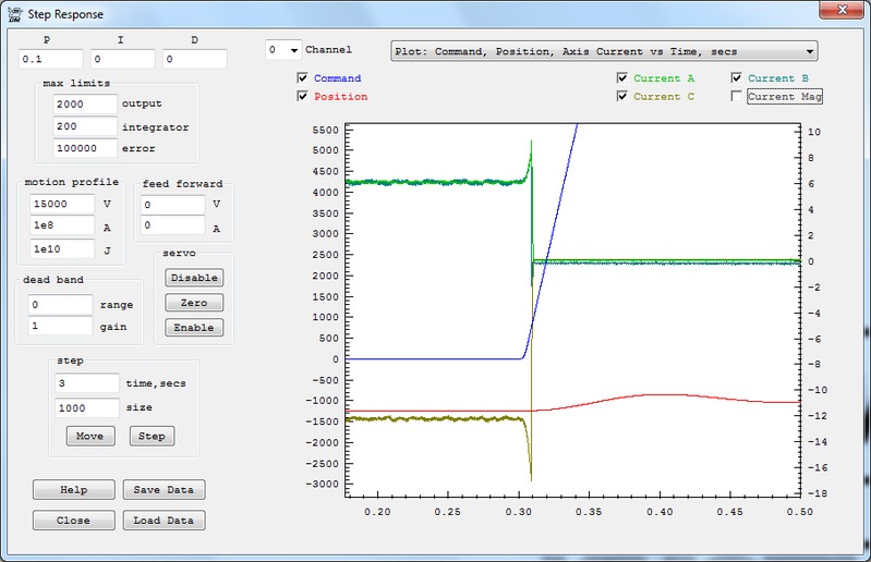
Thanks for all the info. The commutation is not working at all. Your interpretation of step iv is entirely incorrect. This is not servoing. Rather if the commutation is wrong the motor will likely find a spot where full current will generate no torque. Instead of generating torque it will hold position like a stepping motor. The servo sees an error and commands current hoping for the motor to move, but instead the motor just holds the same
position.
I've zoomed into the plot and attached a screen shot. You can see that the desired position (blue) is zero but the actual position (red) is about 1250counts. This results in big coil currents (6, 6, 12 Amps). But the motor is sitting still. As the commanded motion begins the error increases and commands even more current, but very little if any motion occurs. Eventually a current fault occurs and coil currents drop to zero.
In short the commutation isn't working. I think we might need to include the minus sign on the invDistPerCycle as -0.002.
If that doesn't work there might be a bug in the AutoPhaseFind.c for that wiring configuration, and phasing, and encoder direction. It's hard to test all scenarios. Another option is to just use trial and error. With a correct invDistPerCycle of 0.002 (or -0.002 it shouldn't matter) there
should be some commutation offset in a range of 0-5000 that works. If you are within several hundred counts it should work but just not optimally. If it is way off the motor will drive the wrong way and so forth and it should be obvious it is way off. I can usually find it within 10 tries.
HTH Regards TK
| Group: DynoMotion |
Message: 6172 |
From: David Stevenson |
Date: 11/26/2012 |
| Subject: Re: Forward / Reverse Step Response Plots [1 Attachment] |
Hi
Tom,
Success!!!!!
The
invDistPerCycle of -.0002 was the
key. I was able to set the offset to optimize the forward and reverse current
levels after changing the setting and it works very
smoothly.
Thank you
sooo much!!
David
Hi David,
Thanks
for all the info. The commutation is not working at all. Your
interpretation of step iv is entirely incorrect. This is not
servoing. Rather if the commutation is wrong the motor will likely find
a spot where full current will generate no torque. Instead of generating
torque it will hold position like a stepping motor. The servo sees an
error and commands current hoping for the motor to move, but instead the motor
just holds the same position.
I've
zoomed into the plot and attached a screen shot. You can see that the
desired position (blue) is zero but the actual position (red) is about
1250counts. This results in big coil currents (6, 6, 12 Amps).
But the motor is sitting still. As the commanded motion
begins the error increases and commands even more current, but very little if
any motion occurs. Eventually a current fault occurs and coil currents
drop to zero.
In
short the commutation isn't working. I think we might need to include
the minus sign on the invDistPerCycle as -0.002.
If
that doesn't work there might be a bug in the AutoPhaseFind.c for that wiring
configuration, and phasing, and encoder direction. It's hard to test all
scenarios. Another option is to just use trial and error. With a
correct invDistPerCycle of 0.002 (or -0.002 it shouldn't matter) there should
be some commutation offset in a range of 0-5000 that works. If you are
within several hundred counts it should work but just not optimally. If
it is way off the motor will drive the wrong way and so forth and it should be
obvious it is way off. I can usually find it within 10
tries.
HTH
Regards
TK
| | | | | | | | | | | | | | | | | |